Project BackgroundDuring development / research for a project which needs more than 1 UART Port, the common replacement for the Raspberry Pi is the "Arduino MEGA". This is because the MEGA provides 4 UART's which can be used at the same time creating a multi UART device. When using UART on the Raspberry Pi you are very limited on how you work around this limitation, but we also know that the Pi 3B has a built in WiFi & Bluetooth module. In the Raspberry Pi 3B the Bluetooth uses the only UART which further limits the use of the Pi. Most solutions for External UART controllers come as a USB to UART converter, which takes up space and brings the design out of the Raspberry Pi's small form factor. To counteract all the limitations of the Raspberry Pi, we have built a board which simply connects through the Pins on the Raspberry Pi as usual, but include access to extra UART's without limiting the Pi any further or without a special image. Included is our own software which manages, controls, and watches the UART ports. The software comes as a terminal program, and multiple GUI programs, each will report the port location for easy to use manageable hardware integration.
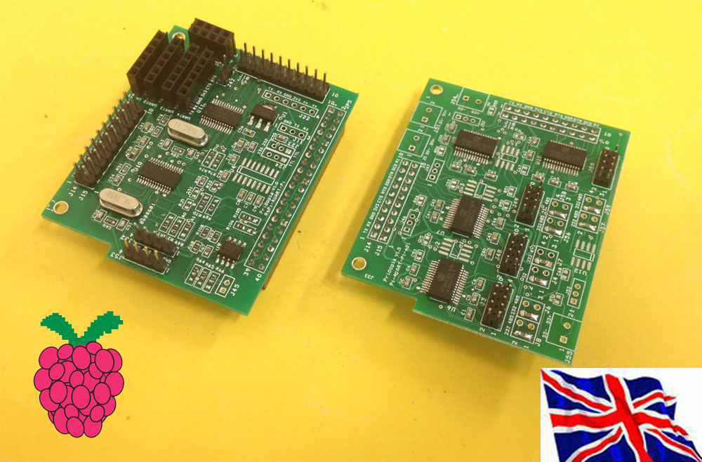
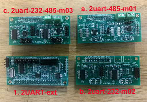
WHAT IS IT? UART HAT is Add-on board for Raspberry Pi which provides one/ two/Four additional RS232 & TTL serial ports with flow control which are 3.3 V compatible in addition to the original Serial Port of Raspberry PI. WHAT IS THE USE OF UART HAT? As we know the Raspberry Pi only has one Serial Port with only one RX and TX, which is primarily used for Debugging and SSH. If we need to connect any serial devices to Raspberry Pi we have to disable debugging and then we need to connect our device. So if you need to connect up a UART device such as a GPS or GSM Modem, you cannot SSH or debug the Raspberry Pi with a serial connection. To overcome the all these problems we have came up with UART HAT which helps to Connects Multiple Serial Devices Like GPS, GSM Modem, Bluetooth 2.0/4.0 module , Arduino Pro Mini, Arduino serials and whole array of devices to Raspberry Pi main board without using the main RX, TX pins on the main board. Serial Port device list I2C to UART HAT board from 1 UART to 2 UART up to 8 UART 2 UART TTL + one UART(Pi) 1 UART TTL + one UART(Pi) with extra 4 GPIO output 1 UART TTL + one UART(Pi) 2 UART TTL + one UART(Pi) with Extension socket 2x RS232 extension Module 2x RS232 /2x RS485 extension Module1. 2uart-Pi-Ze plug in Pi Zero 2. 2uart-Pi-Ze+2uart-232-485-m01 Module plug in Pi Zero 2uart-Pi-Ze-Li demo 3UART demo ( 2 - 2uart-Pi-Ze-Li,1 - Pi) 1. Arduino Mini Pro 2 Bluetooth 2.0 3. Bluetooth 4.0 BLE (Pi) UART Pi Zero HAT plug in B+/ 2B / 3B 4UART products can use up to 8 UART in one Pi 4 UART Pi (4 UART TTL output /HAT EEPROM) with Extension socket 4 UART Pi (4 UART TTL output) 4 x RS232 /4x RS485 Extension module 4x RS232 Extension module4uart-ext board with 4uart-232-485-m01 1. 4 UART Pi (4 UART TTL output /HAT EEPROM) with Extension socket 1a. 4 x RS232 /4x RS485 Extension module 1b. 4x. RS232 Extension module
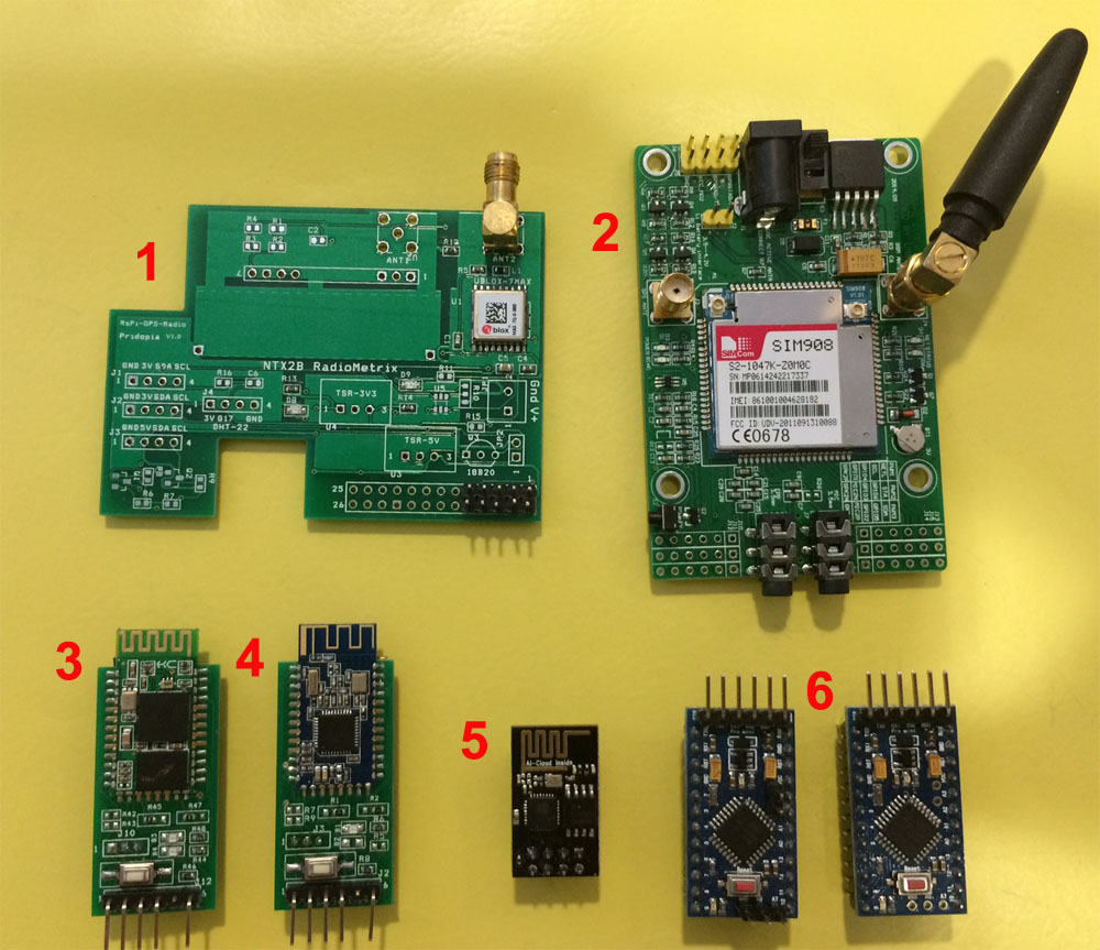
4 UART HAT demo uart1, uart3, uart4 arduino mini Pro x3 Bps: 9600 uart2 bluetooth 2.0 x1 Bps: 38400 9UART demo 8 UART ( 2x 4 UART HAT )+ 1 UART Pi Pi-UART-4-TTL ( 4 UART HAT ) Pi-UART-4-TTL ( 4 UART HAT ) Raspberry Pi 2B Pi-PSU ( Pridopia Pi Power Supply ) SIM908-C EVB 1.0 GPRS+GPS Module ( 2 UART ) ESP8266WiFi module ( 1 UART ) Bluetooth 2.0 ( 1 UART ) Pi-HAT-Lite GPS Module ( 1 UART ) Bluetooth 4.0 BLE ( 1 UART ) arduino mini Pro ( 1 UART Pi ) arduino mini Pro ( 1 UART ) arduino mini Pro ( 1 UART ) |
1. SIM908-C EVB 1.0 GPRS (Port 8 bps 115200 ) 2. SIM908-C EVB 1.0 GPS ( Port 7 bps 115200 ) 3. Bluetooth 2.0 ( Port 6 bps 38400 UART ) 4. ESP8266WiFi module ( Port 5 bps 115200 ) I2C to UART HAT board from 1 UART to 2 UART up to 8 UART 2 UART TTL + 1 Pi UART 2 UART TTL + Pi UART + RS232/RS485 (Full 2 Port DB9 RS232 Output) 2 UART TTL + Pi UART + RS232 (Full 2 Port DB9 RS232 Output) 2 UART TTL ( 1X Full DB9 RS232 & 1X TTL & 232 Output ) & 4 extra GPIO + Pi UARTRS232 DB9 output example 1 UART TTL ( Full DB( RS232 & TTL Output ) + 1 UART TTL + Pi UART 2 UART With RS232/422 (Full DB9 RS232 Output) + 1 Pi UARTExample 1 SIM908-C EVB 1.0 GPRS+GPS Module ( 2 UART ) Pi-HAT-Lite GPS Module ( 1 UART ) Pi-PSU ( Pridopia Pi Power Supply ) Pi-UART-2-TTL ( 2 UART HAT ) Raspberry Pi 2BNeeds 3 UART Signals to control 1 GPS board & GPRS, and GPS board. Example 2 SIM908-C EVB 1.0 GPRS+GPS Module ( 2 UART ) Pi-PSU ( Pridopia Pi Power Supply ) Pi-UART-1-TTL ( 1 UART HAT ) Raspberry Pi 2BGPRS connect to Pi UART & GPS connect to 1 UART HAT GUI Interface for Serial Port Monitoring & Control Cutecom Status for 1 UART HAT ( GPRS 115200 Baud ) Cutecom Status for Pi UART ( GPS 115200 Baud )Example 3 Bluetooth 4.0 BLE ( 1 UART ) Bluetooth 2.0 BLE ( 1 UART ) ESP8266 WiFi Module ( 1 UART, Using Pi RX/TX Signal ) Pi-UART-2-TTL ( Provides 2 UART ) Raspberry Pi 2B Raspberry Pi-PSU ( Power Supply to boards )
1a,2a GUI Interface for Serial Port Monitoring & Control 1. Cutecom Status for UART HAT Port 1 ( Bluetooth 4.0 BLE 9600 Baud ) 2. Cutecom Status for UART HAT Port 2 ( Bluetooth 2.0 BLE 9600 Baud ) 3. Cutecom Status for Pi UART ( ESP8266 WiFi Module 115200 Baud ) Use Raspbian Jessie Image Enable I2C & SPI, Disable Serial Console Port Install Python SMBus and Cutecom; Automatic Login for LightDM
Serial GUI Control Panel Chip Address Location, Channel Number ( 1 / 2 ), TX and RX receive counter, and Serial port Location /dev/pts/X 8. Start : Start UART portAlso provided is a terminal command mode to activate serial ports through a terminal / ssh.
|